Case study 04
Self-Balancing Robot
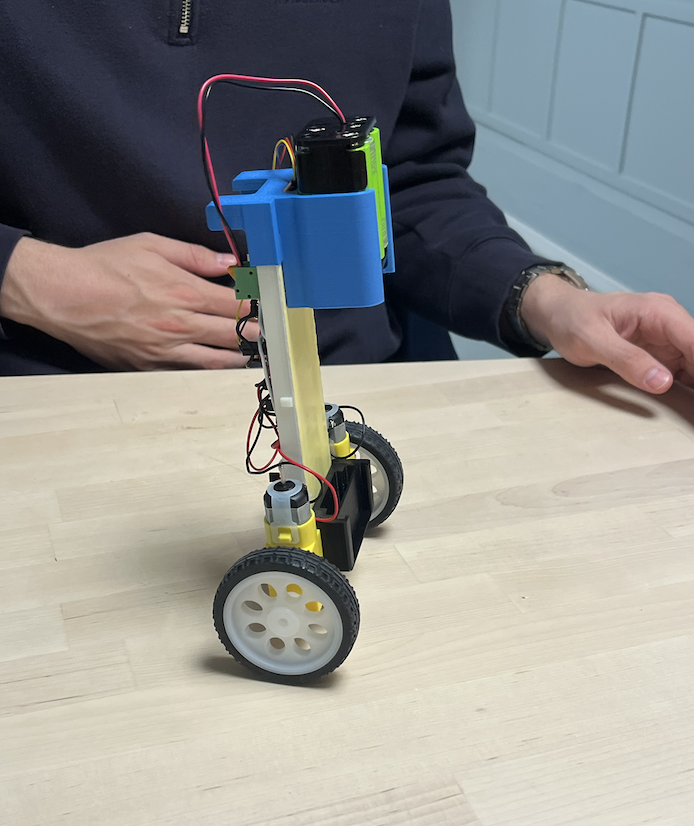
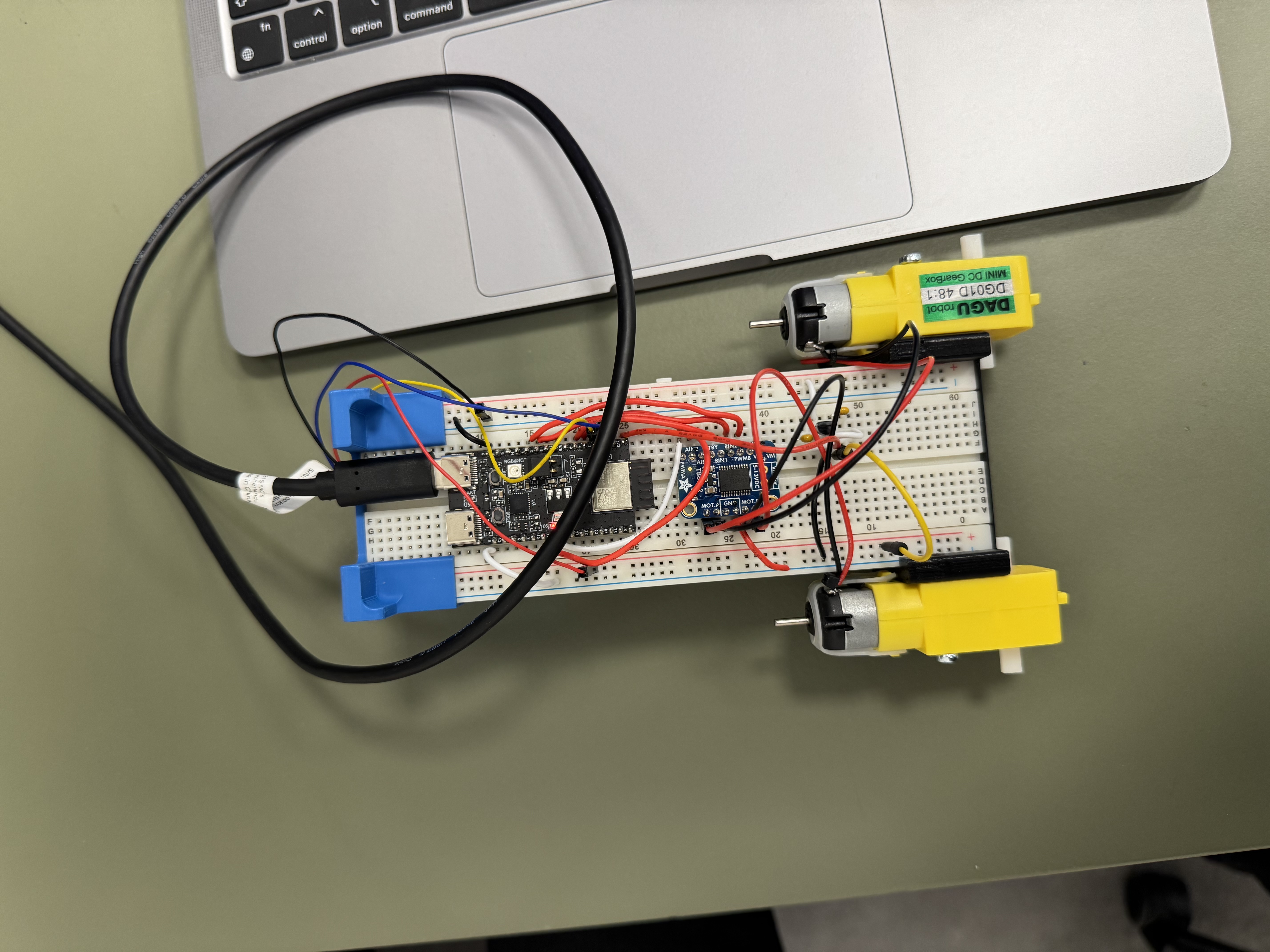
A physical two-wheeled balancing robot developed in TPK4125 at NTNU. The prototype combines BMI270 inertial sensing, Mahony attitude estimation, a configured 10 ms PID sample period and bidirectional PWM motor actuation.
- Discipline
- CONTROL SYSTEMS / IMU / PID
- Course
- TPK4125 — Mechatronics
- Project type
- academic
- Period
- Spring 2026
- Evidence
- Control code
- Team
- 2 mechanical engineering students
- My role
- Embedded control and system integration
01 / Engineering challenge
The system behind the project
Balancing a two-wheeled platform requires low-latency sensing, stable angle estimation and a controller that reacts quickly without creating excessive oscillation. Mechanical mass distribution, motor dead zones and actuator saturation directly affect control performance.
02 / My responsibility
What I personally worked on
Developed collaboratively with Benjamin Færestrand. My work covered embedded programming and system integration across BMI270 acquisition, Mahony-filter angle estimation, QuickPID control, motor-driver commands and iterative physical testing.
Engineering focus
- — PID balance control
- — IMU angle estimation
- — Embedded programming
- — Real-time motor control
Tools and methods
03 / Design and implementation
From concept to working system
- 01
Configure the BMI270 accelerometer and gyroscope at 100 Hz over I²C.
- 02
Fuse acceleration and angular-rate measurements with a Mahony filter and reference the installed sensor orientation to the upright position.
- 03
Configure QuickPID with a 10 ms target sample period using documented Ziegler–Nichols starting values and explicit enable, tilt and saturation safety conditions.
- 04
Convert signed controller output into bidirectional PWM commands with motor dead-zone compensation, then tune and test the integrated physical robot.
04 / Testing and outcome
What the work demonstrated
The project produced a completed physical prototype and a documented closed-loop control implementation. The repository records the BMI270 configuration, Mahony filter, configured 10 ms PID sample period, controller gains, motor mapping and shutdown logic. Because no response plots or controlled disturbance measurements were preserved, the portfolio does not make a quantitative stability or settling-time claim.
05 / Next iteration
How I would develop it further
- 1Quantify settling time and disturbance recovery
- 2Add test plots and a reproducible PID-tuning procedure
- 3Regression-test the post-project sensor fail-safe on the physical robot
- 4Add battery and current monitoring plus a hardware motor-disable path